


- Electromagnetism
- /
- Electrodynamics
- /
- Measuring devices
For circuits maintenance and building, measuring equipments are indispensable. The most important devices are the ones that make measurements of current, voltage and electrical resistance.
Measuring Devices
- Galvanometer:
- Detects small currents passing through it, through a pointer whose deflection is proportional to the current flowing through it. Thus, it is possible to know the current intensity. The greater value that the galvanometer can measure is called full-scale background current.
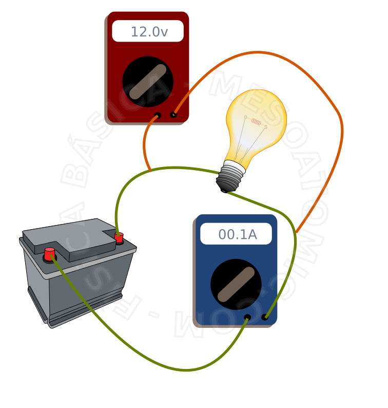
- Ammeter:
- A galvanometer can be used to measure high intensities of electrical current if we use resistors associations and a convenient scale. The internal resistance should be small to not alter too much the current. If the scale is graduated in amps, we have an ammeter. A current meter must be connected in series with the circuit branch where one wants to measure the current intensity.
An ideal ammeter is one that has zero internal resistance.
Illustration of an ammeter connected to a simple circuit, consisting of a resistor and a battery. - Voltmeter:
- It is possible to use a galvanometer as a potential difference meter. To do this, we associate a resistor of high resistance in series with the galvanometer, this resistor is called multiplier. In the event that the galvanometer scale is adapted to measure potential difference in volts, it is called voltmeter. A voltmeter must be connected in parallel with the circuit element whose potential difference is to be measured.
An ideal voltmeter is one that has very large internal resistance (infinite).
Illustration of a voltmeter connected to a simple circuit, consisting of a resistor and a battery. - Wheatstone's Bridge:
- It is a circuit constituting four resistors (with one unknown resistance) connected in diamond form. Between two opposite corners of this rhombus it is connected a power source and a galvanometer (or voltmeter). This circuit allows us to determine the unknown resistance. For this, we must adjust one of the resistors (variable resistance) to balance the bridge. That is, until the galvanometer does not indicate current passage. In this situation, the products of the resistances of opposite branches are equal. The unknown resistance \(R_x\) in a balanced Wheatstone bridge is given by: $$R_x R_2 = R_1 R_3$$ $$R_x = \frac{R_1 R_3}{R_2}.$$

Diagram of the Wheatstone bridge. \(R_x\) is the unknown resistance to be measured, \(R_1\) and \(R_3\) are resistors whose values are known and \(R_2\) is a potentiometer (variable resistor). - Poggendorff's Pot:
- With the aid of a standard known electromotive force cell, an ammeter, a pot, and a homogeneous yarn with a switch, we can determine the electromotive force of an unknown cell. This is done by a circuit called Poggendorff's pot.


